We manufacture a variety of Quik-Pull bundled cable configurations designed to meet the needs of electrical contractors in a range of markets including data centers, automated conveyor systems, solar farm construction, water treatment facilities, and more. Customers will often ask us what are the different applications of a straight versus a spiral configuration.
We are the only manufacturers of the spiral configuration so it is common for us to receive customer inquiries about this unique bundled cable assembly.
Here’s a quick overview on some of the differences and their specific industry uses.
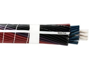
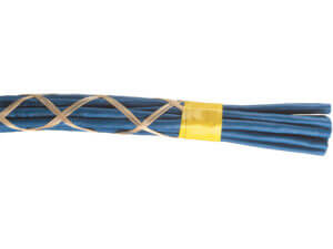
Spiral Configuration
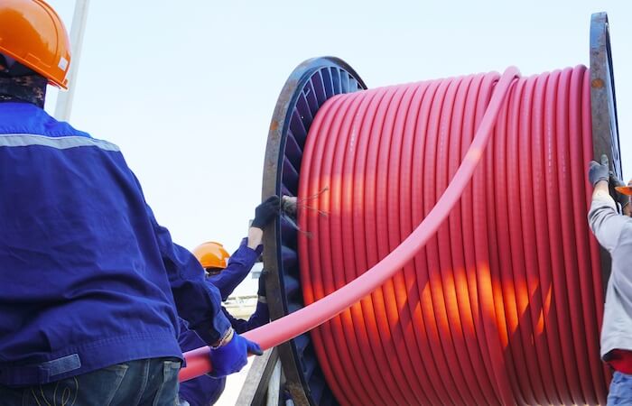
A spiral configuration is a multi-conductor, spiraled together creating a highly flexible cable bundle.
The spiral configuration’s harness and assembly enables it to maintain its roundness in almost all pulls. It is perfect for long pulls where wires must travel along the same path.
The spiral configuration bundle is ideal for “Home Runs” that need to be pulled through conduits, raceways, and gutters. The nylon harness maintains the bundled wirings flexibility while still ensuring that the conductors have enough room to breath.
The spiral configuration assemblies are the most flexible custom bundled cables on the market. Because the spiral configurations retain their roundness and do not change their proportion when bent, they have the lowest chance of hang ups.
Because the spiral assembly preserves its flexibility and roundness under most conditions, it is easier to pull long distances.
INDUSTRY USES:
- For long pulls in conduit where all the conductors will be carried end-to-end.
- Where minimum outside diameter and maximum flexibility are needed.
- Where the overall assembly is to be jacketed.
Additional info:
- The minimum footage per order is 100 feet.
- The wrap is a standard spiral wrap.
- The maximum overall diameter possible is 1.48” (if your OD is larger than this, you would want to choose a straight configuration below).
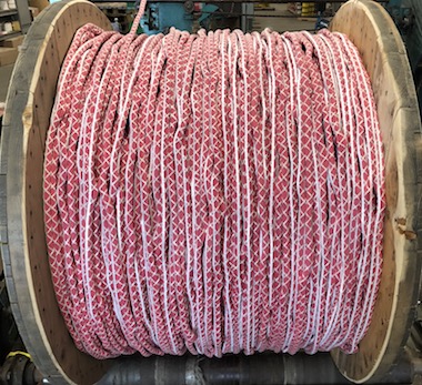
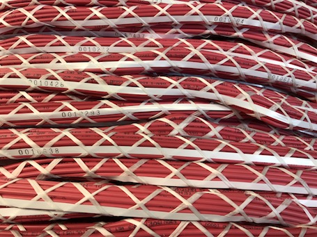
Straight Configuration
In the straight configuration, conductors can be broken out at unspecified and intermediate points along their run with up to 200 conductors on pull-length reels.
The straight configuration consists of individual conductors that can be easily broken out at intermediate points along the run.
In a straight configuration bundle the conductors are laid parallel with no twists. They are ideal for bundles laid in tray, troughs, or other wire management systems where there is no conduit. There is custom printing of any alpha numeric combination along the entire length of the conductor every 1” to 6.”
Since there is custom marking and bundling, all set up on a single reel, this bundled configuration speeds up tray installations while also ensuring there is no left over wire to clean up or left over as surplus inventory.
INDUSTRY USES
- For composites of electronic cables with or without building/fixture wires.
- Where conductors will be broken out at intermediate points along the run.
- Where the assembly will be laid in place, not pulled (wireways or raceways).
Additional info:
- There is no minimum footage requirement.
- The wrap is standard double cross, with optional taped pull tabs for OD’s up to 1”.
- When the overall diameter is 1”or higher, taped pull tabs is recommended.
- The maximum overall diameter possible is 2.1”.
Visit our bundled cable configurations page to learn more about our different cable assembly options.